— FREE — Adding and Replacing Doping
Header
- Files for the tutorial located in nextnano++\examples\basics
basics_1D_doping_adding.in
basics_1D_doping_replacing.in
Introduction
This tutorial continues our discussion about doping, and extend our basic knowledge gained from previous tutorial. After completing this tutorial, you will know more about
replacing impurities by impurities of the same type
removing doping
adding different impurity species to the same region
Overview
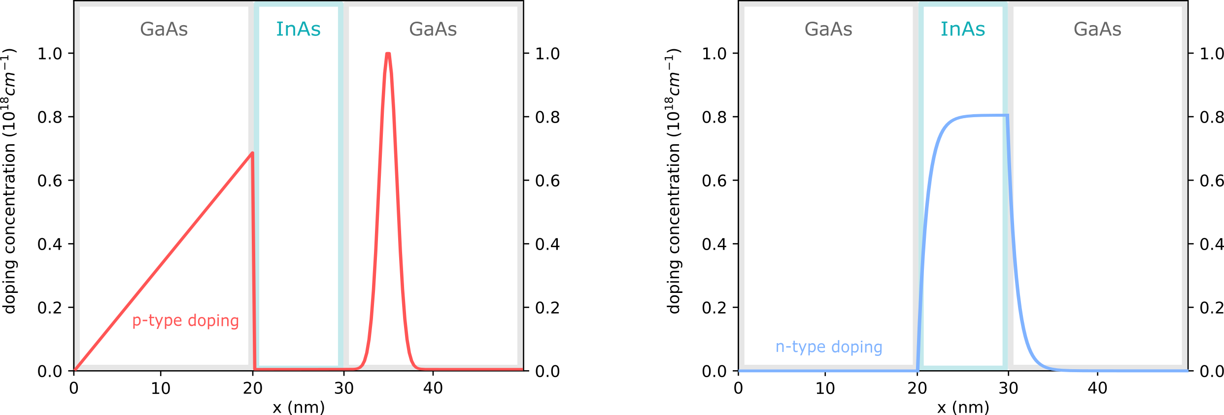
The device structures for this tutorial are shown in Figure 2.4.14.

Figure 2.4.14 GaAs/InAs/GaAs heterostructure with p-type doping (left) and with different doping (right)
1. Replace and remove doping
We will now consider the structure in Figure 2.4.14 (left). You can use the template input file basics_1D_doping_replacing.in.
Specifying regions with dopants
58structure{ # this group is required in every input file
59    output_impurities{ boxes = yes}     # output doping concentration [10^18 cm-3]
60
61    region{
62        binary{ name = GaAs }           # material: GaAs
63        contact{ name = whatever }      # contact definition
64        everywhere{}                    # ranging over the complete device, from x=0.0 nm to x=80.0 nm
65
66        doping{                         # add doping to the region
67            constant{                   # constant doping concentration profile
68                name = "p-type"         # name of impurity
69                conc = 2.0e17           # doping concentration [cm-3]
70            }
71        }
72    }
73
74    region{
75        binary{ name = InAs }           # region InAs
76        line{ x = [ 20.0, 30.0 ] }      # overwriting GaAs at position: x=20.0 nm to x=30.0 nm
77
78        doping{                         # add doping to the region
79            constant{                   # constant doping concentration profile
80                name = "p-type"         # name of impurity
81                conc = 1.0e18           # doping concentration [cm-3]
82                add = no                # overwrites previously defined doping with label "p-type"
83                                        # Note: the default value is add=yes, which adds
84                                        #       dopants to existing dopants
85            }
86        }
87    }
88
89    region{                             # region for deleting dopants
90        line{ x = [ 60.0, 80.0 ] }      # position: x=60.0 nm to 80.0 nm
91            doping{
92                remove{}                # removing all dopants from this region
93            }
94        }
95    }
96}
In this example, we apply the idea of overwriting previous regions to doping. We first define an p-doped GaAs region with impurity concentration \(1.0e18 cm^{-3}\) ranging over the whole device.
Then, we want to overwrite GaAs in the interval between \(x=20 nm\) and \(x=30 nm\) with p-doped InAs, with different impurity concentration.
However, we have to be careful when applying the idea of overwriting previous regions to doping.
By default, the doping is added and not overwritten.
To replace the existing doping, it is necessary to use the specifier add = no.
If we want to remove all dopants from an interval, as it is the case in the region ranging from \(x=60 nm\) to \(x=80 nm\), we have to use remove{}.
Specify impurity species
 97impurities{ # required if doping exists
 98    donor{                      # select the species of dopants
 99        name = "p-type"         # select doping regions with name = "p-type"
100        energy = 0.045          # ionization energy of dopants
101        degeneracy = 2          # degeneracy of dopants
102}
Here, we specify to have only p-type impurities in our device.
Output
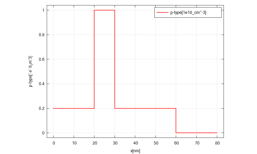
We simulate the device by clicking F8 on the keyboard. In the related output folder
you should find a plot of the concentration profiles (\(\Rightarrow\) Structure \(\Rightarrow\) density_donor.dat)
as shown in Figure 2.4.15

Figure 2.4.15 Doping concentration of donors along the x direction.
2. Add different dopants
We will now consider the structure in Figure 2.4.14 (right). You can use the template input file basics_1D_doping_adding.in.
Specifying regions with dopants
structure{ # this group is required in every input file
    output_impurities{ boxes = yes}     # output doping concentration [10^18 cm-3]

    region{
        binary{ name = GaAs }           # material: GaAs
        contact{ name = whatever }      # contact definition
        everywhere{}                    # ranging over the complete device, from x=0.0 nm to x=80.0 nm

        doping{                         # add doping to the region
            constant{                   # constant doping concentration profile
                name = "p-type-I"       # name of impurity
                conc = 2.0e17           # doping concentration [cm-3]
            }
        }
    }

    region{
        binary{ name = InAs }           # region InAs
        line{ x = [ 20.0, 30.0 ] }      # overwriting GaAs at position: x=20.0 nm to x=30.0 nm

        doping{                         # add p-doping to the region: the existing "p-type-I" doping is not overwritten
            constant{                   # constant doping concentration profile
                name = "p-type-II"      # name of impurity
                conc = 1.0e18           # doping concentration [cm-3]
            }
        }
    }

    region{                             # region for adding doping
        line{ x = [ 60.0, 80.0 ] }      # position: x=60.0 nm to 80.0 nm

        doping{                         # add n-doping to the region: the existing "p-type-II" doping is not overwritten
            constant{                   # constant doping concentration profile
                name = "n-type"         # name of impurity
                conc = 4.0e17           # doping concentration [cm-3]
            }
        }
    }
}
Here, we crete GaAs and InAs each with specific doping. Note that InAs replaces GaAs on the interval x = [ 20.0, 30.0 ], while the doping definitions do not influence each other. Also, on the interval x = [ 60.0, 80.0 ], n-type doping is simlpy added.
It should be emphasized that the option doping{...add=no..} is only applicable to dopants of the same dopant type.
Remember: a doping type, i.e. chemical element, is associated with one particular name.
If we wish to replace dopants by a different dopant type, we would need to remove the existing dopants first and then add the new ones.
Specify impurity species
 97impurities{ # required if doping exists
 98    acceptor{                   # select the species of dopants
 99        name = "p-type-I"       # select doping regions with name = "p-type-I"
100        energy = 0.045          # ionization energy of dopants
101        degeneracy = 4          # degeneracy of dopants
102    }
103
104    acceptor{                   # select the species of dopants
105        name = "p-type-II"      # select doping regions with name = "p-type-II"
106        energy = 0.045          # ionization energy of dopants
107        degeneracy = 4          # degeneracy of dopants
108    }
109
110    donor{                      # select the species of dopants
111        name = "n-type"         # select doping regions with name = "n-type"
112        energy = 0.045          # ionization energy of dopants
113        degeneracy = 2          # degeneracy of dopants
114    }
115}
For every impurity type, we have to add a new accceptor{}/ donor{} group.
Output
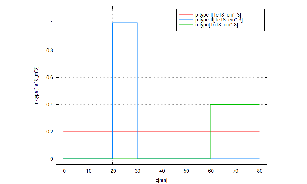
We simulate the device by clicking F8 on the keyboard. In the related output folder
you should find a plot of the concentration profiles (\(\Rightarrow\) Structure \(\Rightarrow\) density_donor.dat)
as shown in Figure 2.4.16

Figure 2.4.16 Doping concentration of donors/ acceptors along the x direction.
Important things to remember
The nextnano++ tool treats each doping type associated with a particular
nameseparately, thus they do not overwrite each other.only doping associated with the same
namecan overwrite each other (add = no)
Last update: 16/07/2024